Monday, November 7, 2016

One RGB model, many RGB spaces

The RGB (Red, Green, Blue) color model dates back to 1860 and the Young-Helmholtz trichromatic theory of color vision. In fact, all color models are tied to human color vision. Color models that define a light source, such as RGB, are additive. Color models for paints and objects, such as CMYK, are subtractive. Additive color models combine colors. Subtractive color models define the color refracted when a photon of light strikes a surface.

The RGB color model does not provide a colorimetric definition of red, green, and blue. The model defines colors in reference to the primary colors.

Figure 1 - RGB Color Model
(credit: Wikipedia)
RGB specifies a color by defining its location within a three dimensional matrix. Each index has a value that is between 0 and 255. This provides for a maximum of 16,777,216 possible colors. However, humans with normal color vision can only detect around ten million colors.

Human color perception is based on the response of the three cone types to a photon of light. Each of the cone types have their own frequency response curve for responding to photons, as shown in Figure 2.

Figure 2 - Human cone response

RGB color space

With the specification of the chromaticity of red, green and blue, the color model becomes a color space. Chromaticity defines the quality of a color, without referring to luminescence. The two parameters for chromaticity are hue and chroma (also called saturation, intensity).

To define the boundaries of the RGB color space, we need to know the chromaticity for three points: red (1,0,0), green (0,1,0) and blue (0,0,1). The problem is that the RGB model lacks definitions for chromaticity or luminosity.  For a solution to this problem, we need to look at the color spaces defined in 1931, by the International Commission on Illumination (CIE). The 1931 CIE color spaces define the quantitative link between the wavelength of light and the human perception of color. The CIE 1931 color spaces are foundation on which modern color spaces are built. They are also important to understanding the mechanics behind colorblind simulation. For the purpose of this article, the important CIE color spaces are described below.

CIE XYZ color space

The CIE XYZ color space is a device independent color space that represents all the color sensations experienced by an average person, as shown in Figure 3. It serves as a standard reference for other color spaces.

Figure 3 - CIE XYZ color space (colors displayed are limited to sRGB color space)
(credit: Wikipedia)
Figure 3 is actually a chromaticity diagram that compresses the three dimensional color space for the three different cone types into two dimensions. The enclosed space represents the gamut of human colors. The curved edge of the diagram shows the light frequency in nanometers. The straight edge is known as the line of purples (colors for which there is no single monochromatic source).

CIE RGB color space

Unlike the CIE XYZ color space, the CIE RGB color space defines a the color space resulting from the mixing of three monochromatic light sources. It was the first color space to be based on adding three primary colors. Figure 4 illustrates the gamut for the CIE RGB color space.

Figure 4 - CIE RGB color space
(credit: Wikipedia)
The triangle in Figure 4 defines the gamut for the CIE RGB color space. The circle with the label "E" is the white point. Since computers did not exist in 1931, this color space served as a reference study for color vision research.

CIE L*A*B* (CIELAB) color space

It is important to keep in mind that this entire discussion revolves around human color vision. The Young-Helmholtz trichromatic theory is not the only color vision theory. In the late 19th century, Ewald Hering developed the opponent-process theory of color vision. The opponent-process theory holds that the cone photoreceptors combine to form three opposing color pairs: blue/yellow, red/green/, and black/white. The opponent-process theory explains human color experience, such as why we don't see "bluish yellow" or "reddish green". It all helps explain why individuals who are dichromatic confuse either red and green or blue and yellow. The stages theory of color vision holds that the trichromatic theory functions at the photoreceptor level, while the opponent-process theory functions at the neural level.

In 1976, CIE released the CIE L*A*B* color space, which is based on the opponent-process theory of color vision. The vertical axis represents lightness (L*), with values ranging from 0 (black) to 100 (white). The range of the values for a* and b* are usually from +100 to -100 or +127 to -128. Figure 5 illustrates the CIELAB color space (note: there is a label error in the diagram, as Blue should be -b).

Figure 5 - CIE L*A*B* color space
(credit: Wikipedia)
The CIELAB color space is device independent, and incorporates the entire gamut of human perceivable  colors. The CIELAB gamut does include colors that are outside the human gamut. Since it does incorporate the entire human gamut of colors, CIELAB is often used to convert colors from one color space to another.

Device dependent color spaces

The above color spaces were all device independent. In regards to device dependent color spaces, this article only covers the most popular of the current digital RGB color spaces. Besides the chromaticity of the three primary colors, a color space requires a white point. A white point is that point where the chromaticity coordinates produce the color white. The two most common illuminants used to define a white point are D50 (horizon light) and D65(noon daylight).

Figure 6 - Color space comparisons
(credit: Wikipedia)
 Figure 6 compares the most common color spaces in use. Except for SWOP CMYK (a typical printer color space), the color spaces are all RGB. Every RGB color space shown in Figure 6 uses the same range of values to address colors. For example, the color code red=120, green=154, blue=48 references a different color in each color space. The CIELAB color space acts an intermediary color space for color space conversion.

sRGB color space

Created by Microsoft in 1998, sRGB has the smallest gamut of all the color spaces. sRGB acts as the least common denominator. In Web design, CSS uses sRGB. The common format across all Web browsers is sRGB. As of this writing, Android and iOS only support sRGB (iOS 10 also supports DCI-P3 on the iPad Pro 9.7").

Adobe RGB

With its larger color gamut, Adobe RGB is probably the most popular color space for working with images. For mobile devices and Websites, Adobe RGB images must be converted to sRGB. 
Without conversion to sRGB, Adobe RGB images are darker and muted.

Colormatch RGB

This color space was originally designed for the PressView line of calibrated displays. The gamut for Colormatch  is only slightly larger than sRGB in the blue-green region, but a smaller gamut in the red-blue region.

ProPhoto RGB

Eastman Kodak designed the ProPhoto (ROMM) color space as a RGB color space for editing images. The ProPhoto primaries are not linked to any monitor specification. The large gamut minimizes the loss of color. However, the ProPhoto gamut does have out-of-gamut colors for human vision. ProPhoto uses the D50 white point, and not D65.

Color profiles versus color spaces

A color profile is an implementation of a color space. According to the International Color Consortium (ICC - CIE in French), profiles define the color attributes for a particular device or viewing requirement via a map between the device or color space and a profile connection space (PCS). The PCS is either CIE L*A*B* or CIE XYZ. Mappings can be specified using either tables or a series of transformation parameters.

 When a color profile is embedded in a file, the file is said to be tagged. Color management is the controlled conversion between color spaces. Lacking color management, sRGB is the default color space. Web browsers do not support color management. Thus, sRGB is the default color space.

Android does not support color management. However, Samsung's "Screen mode" performs color management. The options vary depending on the whether the device has an AMOLED screen, and the Android version. For AMOLED devices:

  •  "Basic" or "Standard" is sRGB without modifications.
  •  The "Adaptive display" mode boosts the brightness for viewing screen in daylight, and only applies to a few applications.
  •   The "Photo" or "Professional photo" seems to support Adobe RGB, as it has a much larger gamut.
  • The "Cinema" mode appears to support a gamut similar to DCI-P3.

For reasonable consistency across all devices and Web browsers, the sRGB color space is still the only common denominator. Without color management, an device automatically displays images in all color spaces as if they used the sRGB color space.

Conclusion

Not only is color an illusion, color consistency across all devices is illusive. Even an sRGB image will appear differently on different devices. Not only are there hardware variations, variations in screen brightness and surrounding light change the appearance of colors. The only solution is to color calibrate every display device. Color spectrometers are rather expensive, so the only other choice is to accept that a certain degree of color variation across devices is a reality. 


Sunday, September 4, 2016

Are colorblind simulation models accurate?

This article has been replaced with

Accurate in what sense? The colors produced in an image do not determine accuracy, for we know that color is an illusion. What counts is the ability to discriminate between different shades of color. We do not know the color a person actually sees, but we do know that protans and deutans confuse shades of red and green. Consequently, the color generated by a colorblind simulator is not important. What is important is that the simulated color reflects the same confusion as experienced by an individual with Color Vision Deficiency (CVD).

Test Environment

Selecting a color blindness test was the first challenge. My goal was to use a test that could be automated. While it is a common test, the Ishihara Test Plates do not meet this criteria, and are only used for initial screening. The Farnsworth-Munsell 100 Hue (FM-100) test meets the criteria, as does the Farnsworth Dichotomous (D-15 Panel) test. For the initial round of testing, I used the D-15 Panel, with a minimal amount of coding and a lot of manual data collection.

The FM-100 and D-15 Panel test are classed as hue discrimination, or arrangement, tests. As the name implies, these tests use the Munsell color system. The Munsell color system is a three-dimensional system based on hue, chroma, and value. On the other hand, the RGB color system has no sense of chromaticity or luminosity. There is no nice one-to-one conversion between Munsell and RGB. Yet, there are computer based tests for the FM-100 and D-15 panel tests that use the RGB color system.

Both Colblindor and ColorMunki provide Web versions of the FM-100 Hue test. Both sites use the same RGB colors for the each of the four panels. Daniel Flück of Colbindor created the original on-line version of the D-15 Panel test. Color Blindness also offers this test, but the RGB colors are different. In my tests, the Colbindor version is referred to as D15A, and the Color Blindness version is D15B. The two versions produce different results.

Since the Farnsworth tests are all based on the hue of a color, the RGB colors were converted to HSV to obtain the hue. The Munsell colors used by Farnsworth have a chroma equal to 6 and a value equal to 6. The only variable is the hue. When the RGB colors are converted to HSV the values for saturation and value are not constant. The same holds true for saturation and luminosity under the HSL color system.

The FM-100 hues for normal vision are correctly spaced and form a color wheel. While the hue values were different, the normal vision hues for both versions of the D-15 test were OK. Under the Munsell color system, the hue is a integer value between 1 and 360. With HSV, or HSL, it is a float value such that the hue >= 0 and <= 359. Rounding the float value to an integer produced too many duplicate simulation values. Changing the float to ###.## greatly reduced the duplication problem. There are still cases where a model generates the same RGB value for two caps, or the same hue for different RGB values. The hue values were generated by a Quick Test feature that is only enabled in the debug mode of my Colorblind Simulator Pro app.

Scoring the tests

I initially scored each test using the traditional scoring sheets from Richmond Products. While these score sheets were designed for binocular vision tests with a retest, they work perfectly for scoring and comparing the four models that were the subjects of my tests. When compared with the quantitative results, the graphic drawings provide additional clues into the behavior of a model.

The article "A Quantitative Scoring Technique for Panel Tests of Color Vision" by Algis J. Vingrys and P. Ewen King-Smith includes the source for a scoring program. This program forms the basis for the scoring of the on-line tests described above. While Daniel Flück created a JavaScript version of the PC BASIC program, I created a Java version.

The tables in the article by Vingrys and King-Smith include a column for TCDS (Total Color Difference Score). The calculation of this score is not part of the BASIC program included in the article. Although the book "Borish's Clinical Refraction" by William J. Benjamin provides the color difference tables used by Bowman, the calculation of TCDS is still a problem for the following reasons:
  1. The cap differences are based on the Munsell colors. For example, the Munsell color difference (Delta-E) between the Pilot cap and Cap 1 is 9.4. For the RGB color system, the Delta-E for Colblindor (D15A) is  9.491 and 8.8034 for Color Blindness (D15B). The differences in Delta-E values could have an impact on the ability to distinguish colors.
  2. Using the Bowman tables described in Benjamin's book, the TCDS for normal vision is 117. However, Vingrys and King-Smith show a normal vision TCDS of 165, with no explanation of the difference with Bowman. Without a formula for calculating TCDS, comparative analysis is not possible.

Simulator models tested

All tests are limited to the four models that are part of my Colorblind Simulator Pro app, debug version 1.1.1 build 23. The Quick Test activity of the debug version includes additional output that is not part of the released version. This output was designed for model testing. A modified version of this feature may appear in a future release.

Meyer-Greenberg-Wolfmaier-Wickline (MGWW)

The first computer simulation work was done in 1988 by Gary W. Meyer and Donald P. Greenberg. The goal of their study was to create a digital means of administering the Farnsworth-Munsell 100 Hue test. Anyone wishing to have a better understanding of the FM-100 test should read this article.

The study by Meyer and Greenberg:
  • Converts RGB to CIE XYZ color space
  • Adjustments were made to keep output RGB values within the range of 0 to 255.
While the Meyer and Greenberg study was published in 1988, Thomas Wolfmaier wrote a Java applet around 1999 that used their study to create a CVD simulator. Two years later Matthew Wickline published his improved version of Wolfmaier's code. Thus, this model is referred to as MGWW. The Colorblind Simulator Pro app implements Wickline's code.

Brettel-Vienot-Mollon (BVM)

In 1997, Hans Brettel, Francoise Vienot and John D. Mollon published Computerized simulation of color appearance for dichromats. Even though it was published 11 years earlier, Brettel-Vienot-Mollon do not reference the work of Meyer-Greenberg. The differences between BVM and MGWW are:
  • BVM converts RGB to LMS and not CIE XYZ
  • The BVM algorithm makes no attempt to limit out-of-bound conditions for RGB values
  • The goal of BVM was to build a simulator for images
  • Based on reports by unilateral dichromats (one normal eye and one dichromatic eye)

Machado-Oliveira-Fernandes (MOF)

While MGWW and BVM focused on dichromats, Mechado-Oliveira-Fernandez sought to create a simulation model for both dichromats and anomalous trichromats. Where MGWW and BVM follow the Young-Helmholtz theory of color vision, MOF follow the stage theory. The stage theory, or zone theory, holds that the Young-Helmholtz theory works at the photo-receptor level, but signals are then processed according to Hering's component theory.

For anomalous trichromacy, MOF theorize that the degree of deficiency depends on the amount of shift in the cone wavelength sensitivity. For dichromacy, the deficient cones are replaced by cones with another frequency range.

MOF created a C++ version of the FM100 test to verify their theory. Their test group consisted of 17 male subjects with normal vision and 13 male subjects with protanopia, protanomaly, deuteranopia or deuteranomaly. The test group did not include any tritans.

The only source code available is the precalculated tables provided in the above article. The lack of complete source code makes it difficult to reproduce their test results.

Linear 

The linear model is a precalculated version of the BVM model. Loren Petrich provides the model in his source code, with no references as to its origin. Sometimes the output matches the output from BVM, and other times it is radically different.

Test results

All tests were scored using both the 15 Disc Color Vision Test score sheets, and the quantitative methods of Vingrys and King- Smith. Besides the Vingrys and King-Smith article, the Farnsworth and Lanthony Test Instructions provides illustrations for interpreting the charts. The following table provides a baseline for interpreting Vingrys and King-Smith scores.

Table 1 - Results of vector analysis

Type of Cap Arrangement Angle Major Radius Minor Radius TES S-Index C-Index
Normals:


No error 62.0 9.2 6.7 11.4 1.38 1.00
Minor error -12.1 9.8 9.2 13.4 1.07 1.06
Tritan error -80.8 16.3 6.4 17.5 2.07 1.77
Congenital CVD:


Protanope 9.7 38.9 6.4 39.4 6.12 4.21
Deuteranope -8.8 35.6 7.4 36.4 4.82 3.86
Tritanope -86.8 28.2 6.0 28.8 4.74 3.06
Deuteranomal -8.7 20.5 12.2 23.9 1.68 2.22
Acquired color vision loss:


DIDMOAD 81.7 27.7 25.4 37.6 1.09 3.00


Following are the guidelines for interpreting the Vingrys  and King-Smith data used in this article:
  • Angle: The confusion angle identifies the type of color deficiency. According to Vingrys and King-Smith, an angle +3.0 and +17.0 indicates protanopia, a deuteranopia angles range between -4.0 and -11, while tritan have an angle greater than -70. Colblindor expands the ranges: protan defect begins at +0.7, from +0.7 to -65 is a deutan defect, and below -65 is a tritan defect.
  • Major and minor radius: Vingrys and King-Smith use the moments of inertia method to determine color difference vectors. The major and minor moments of inertia are converted to major and minor radii to preserve the same unit of measure as used for the angles. These values can be used to determine the severity of the defect.
  • Total Error Score (TES): In math terms, TES is the root mean square of the sum of the major and minor radii. Scores have an approximate range of 11 to 40+, with higher values indicating greater severity.
  • Selectivity Index (S-index): The S-Index is the ratio of the major and minor radii. Values less than 1.8 indicate normal vision, or random values.
  • Confusion Index (C-Index): The C-Index the major radius of the subject and the minor radius for normal vision. The dividing line between normal and defective is 1.60.
A total of 12 tests were conducted. For these tests, the percentage of color blindness was 100%, as the MGWW and BVM studies only included those who were tested as normal, protanopia, deuteranopia, or tritanopia. For each type of color blindness, tests were conducted using a gamma of 1.0 and 1.2 (for Android, 1.2 is the equivalent of 2.2 in the original studies). For each gamma value, a separate test was conducted for the two different D15 RGB color ranges (D15A and D15B).

Three questions tested:
  1. Does gamma make a difference?
  2. Do D15A and D15B produce the same results?
  3. Which simulation models pass the tests?
As we shall see, every model is different.

Test results for protanopia

Following are the Vingrys and King-Smith scores for the protanopia tests:

Table 2 - Protanopia test scores

D15 Gamma Percent Model Angle Major Radius Minor Radius TES S-Index C-Index
A 1.0 100 MGWW 12.8 43.5 17.0 46.7 2.55 4.71
A 1.0 100 BVM 3.4 36.6 13.3 38.9 2.76 3.96
A 1.0 100 MOF 0.2 35.6 13.0 37.9 2.74 3.85
A 1.0 100 Linear 2.4 35.4 10.1 36.8 3.52 3.83
A 1.2 100 MGWW 11.6 42.1 17.1 45.5 2.46 4.56
A 1.2 100 BVM 8.3 35.6 10.8 37.2 3.29 3.86
A 1.2 100 MOF 8.6 31.6 16.3 35.6 1.94 3.42
A 1.2 100 Linear 2.1 31.0 13.7 33.9 2.26 3.35
B 1.0 100 MGWW 13.0 42.2 17.2 45.6 2.46 4.57
B 1.0 100 BVM 1.5 33.8 12.7 36.2 2.66 3.67
B 1.0 100 MOF 12.6 40.4 12.8 42.4 3.17 4.38
B 1.0 100 Linear 9.6 34.7 14.4 37.6 2.42 3.76
B 1.2 100 MGWW 6.7 44.0 17.2 47.2 2.55 4.76
B 1.2 100 BVM -12.6 31.9 13.4 34.6 2.39 3.46
B 1.2 100 MOF 5.7 31.3 12.7 33.8 2.47 3.39
B 1.2 100 Linear 7.8 31.5 14.4 34.7 2.20 3.41

Following are a few notes regarding the above scores:
  1. MOF, for D15B and a gamma of 1.0, and MGWW, in all tests,  had high (40+) TES values, which indicate a strong protan defect. In all other test cases, the TES indicated a lesser degree of severity. The C-Index reflects the TES.
  2. For D15A and a gamma of 1.0, the BVM, MOF, and Linear models returned results that were consistent with deuteranomaly and not protanopia. For D15A, the angles show that gamma does make a difference for BVM and MOF. These models return the correct results when using the CRT settings for a dim light background environment (gamma 1.2). However, the D15B results show BVM sliding from deuteranomaly to deuteranopia with a gamma change. The wrong answer in both tests.
  3. The linear model returns values closer to deuteranomaly than to protanopia.
  4. Neither gamma nor RGB colors make a difference to MGWW.
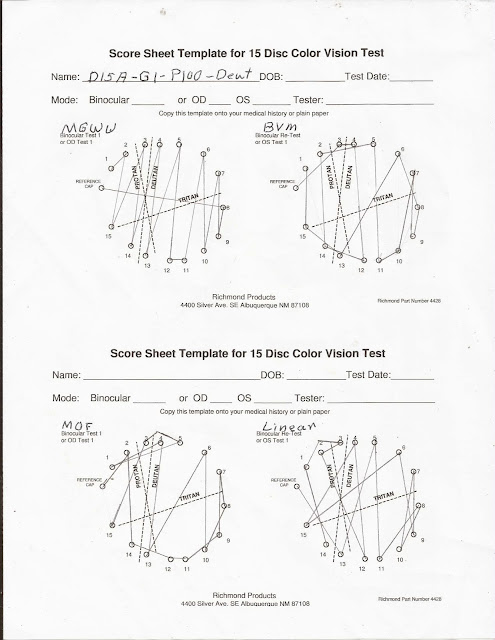
The following D15A diagrams confirm the above data.

Colors D15A with Gamma 1.0 Protanopia
Figure 1 - D15A Gamma 1.0 Protanopia
These diagrams illustrate that  each model creates a unique color wheel. The resulting color wheel is not like turning a dial, but has transitions. It is the transitions that create confusion.

In Figure 1, MGWW illustrates a classical diagram for protanopia due to the number of lines that are parallel to to the dashed protan line. While BVM and MOF have low angles, they have lines that are parallel, or nearly parallel, to the protan lane. The linear model, on the other hand, has clear deutan lines.

As shown in Figure 2, gamma has a variable impact.

Colors D15A with a gamma of 1.2 for protanopia 100 percent
Figure 2 - D15A Gamma 1.2 Protanopia
While the angle is slightly smaller in Figure 2, MGWW still provides a clear definition of protanopia. Although the angles are in the protan range, the graphs for BVM and MOF show clear deutan lines. Again, the Linear model leans towards deuteranomaly.

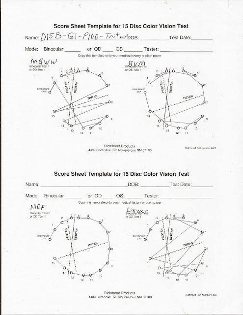
The problem with converting the Munsell color system to RGB resulted in two sets of RGB values for the Farnsworth D15 test. The graphs in Figure 3 and those in Figure 1 illustrate the difference with a gamma of 1.0.

Diagrams based on D15B colors with a gamma of 1.0 for protanopia.
Figure 3 - D15B Gamma 1.0 Protanopia
In Figure 3, MGWW remains essentially the same as Figure 1. BVM shows both protan and deutan lines, which results in a low angle leaning towards deuteranomaly. Both the MOF and Linear models indicate protanopia.

Figure 4 has an interesting twist.

Colors D15B with Gamma of 1.2 for protanopia.
Figure 4 - D15B Gamma 1.2 Protanopia
Changing colors does not impact on MGWW. With no clear protan lines, BVM went to deuteranopia. MOF has both protan and deutan lines, but scores as protan. The Linear model scores as protan with D15B colors.

Test results for deuteranopia

For deuteranopia, most angles move from positive to negative as shown in Table 3.

Table 3 - Deuteranopia test scores

D15 Gamma Percent Model Angle Major Radius Minor Radius TES S-Index C-Index
A 1.0 100 MGWW -10.2 38.2 20.3 43.2 1.88 4.13
A 1.0 100 BVM -6.5 30.2 14.7 33.6 2.06 3.27
A 1.0 100 MOF -21.4 28.2 15.8 32.3 1.79 3.05
A 1.0 100 Linear -4.5 37.3 18.9 41.8 1.97 4.04
A 1.2 100 MGWW -10.2 38.2 20.3 43.2 1.88 4.13
A 1.2 100 BVM 2.7 34.8 17.3 38.9 2.01 3.77
A 1.2 100 MOF 4.1 25.8 13.0 28.8 1.99 2.79
A 1.2 100 Linear -14.8 29.9 15.3 33.6 1.95 3.24
B 1.0 100 MGWW -7.9 38.0 20.1 43.0 1.89 4.12
B 1.0 100 BVM -8.6 34.0 16.5 37.8 2.06 3.68
B 1.0 100 MOF -9.5 34.7 14.5 37.6 2.39 3.75
B 1.0 100 Linear 6.3 36.4 13.2 38.8 2.75 3.95
B 1.2 100 MGWW -7.9 38.0 20.1 43.0 1.89 4.12
B 1.2 100 BVM -17.5 31.7 14.7 35.0 2.15 3.43
B 1.2 100 MOF -10.9 23.5 13.5 27.1 1.74 2.54
B 1.2 100 Linear -6.8 31.0 17.4 35.5 1.78 3.35

Notes regarding deuteranopia test scores:
  1. For MGWW, the angles change somewhat between D15A and D15B, but the S-Index and C-Index change very little. MGWW remains the most consistent model.
  2.  BVM only returns deuteranopia scores with D15B, while scoring as deuteranomaly with D15A.
  3. Twice the S-Index for MOF moves to the normal/random range. The only correct score for MOS is D15B at gamma 1.0.
  4. The Linear models returns two scores in the deuteranomaly range, and one score as protanopia. Only D15A at a gamma 1.2 returned a deuteranopia score.
 The drawings will help clarify what is happening with the BVM, MOF and Linear models.

D15A Gamma 1.0 Percent 100 Deuteranopia
Figure 5 - D15A Gamma 1.0 Deuteranopia
In Figure 5, MGWW represents a standard deuteranopia pattern. The BVM and Linear models are better representations of deuteranomaly than deuteranopia. The low S-Index raises questions about the MOF model, but it does have one deutan line, which makes it a mild case of deuteranomaly.

D15A Gamma 1.2 Percent 100 Deuteranopia
Figure 6 - D15A Gamma 1.2 Deuteranopia
As shown in Figure 6, changing the gamma had very little impact on MGWW. BVM has both protan and deutan lines. For BVM, a gamma of 1.2 accentuated the deuteranomaly. The graph for the MOF model explains the low S-Index and low C-index. MOF represents low deuteranomaly, and not deuteranopia. Increasing the gamma made the scores worse for MOF. The Linear model actually benefitted from the increased gamma, with more lines aligned with the deutan axis.

D15B Gamma 1.0 Percent 100 Deuteranopia
Figure 7 - D15B Gamma 1.0 Deuteranopia
As shown in Figure 7, MGWW exhibited a minor change from D15A to D15B, but the graph is still that of a deuteranope. The BVM and MOF models both produced better deutan lines, as express in the angles. Meanwhile, the Linear model became a protan. Does changing the gamma to 1.2 make a difference?

Model graphs for D15B Gamma 1.2 Percent 100 Deuteranopia.
Figure 8 - D15B Gamma 1.2 Deuteranopia
In Figure 8, MGWW produced the same results as Figure 7. BVM and MOF both have deutan lines that justify their deuteranopia score. The Linear models still has both deutan and protan lines, but scores as a deuteranomaly with a gamma of 1.2.

Test results for tritanopia

Tritanopia raises serious questions regarding model behavior as shown in Table 4.

Table 4 - Tritanopia test scores

D15 Gamma Percent Model Angle Major Radius Minor Radius TES S-Index C-Index
A 1.0 100 MGWW -80.0 30.7 14.2 33.9 2.16 3.33
A 1.0 100 BVM -80.1 27.1 15.2 31.1 1.78 2.93
A 1.0 100 MOF 62.0 9.2 6.7 11.4 1.38 1.00
A 1.0 100 Linear -87.2 28.2 12.9 31.0 2.19 3.05
A 1.2 100 MGWW -85.5 27.6 15.8 31.8 1.75 2.79
A 1.2 100 BVM -85.7 25.2 18.8 31.4 1.34 2.73
A 1.2 100 MOF 62.0 9.2 6.7 11.4 1.38 1.00
A 1.2 100 Linear -87.7 28.6 15.5 32.5 1.84 3.10
B 1.0 100 MGWW -87.2 28.1 14.9 31.8 1.88 3.04
B 1.0 100 BVM -75.5 20.8 11.9 23.9 1.75 2.25
B 1.0 100 MOF 62.0 9.2 6.7 11.4 1.38 1.00
B 1.0 100 Linear -81.0 27.2 13.8 30.5 1.97 2.94
B 1.2 100 MGWW -87.1 27.8 14.9 31.6 1.87 3.01
B 1.2 100 BVM -82.8 30.5 14.4 33.8 2.12 3.31
B 1.2 100 MOF 62.0 9.2 6.7 11.4 1.38 1.00
B 1.2 100 Linear -78.6 35.0 11.3 36.8 3.1 3.79

Notes on Table 4:
  1. Only MGWW model passed the tritanopia tests.
  2. MOF tested as a normal with a rotated color wheel.
  3. The BVM model tested closer to tritanomaly than tritanopia. For BVM,the S-Index was below 1.80 in 3 out of the four tests.
  4. The Linear model actually scores better than BVM for tritanopia.
The charts should confirm the above model behavior.

Model graphs for D15A Gamma 1.0 Percent 100 Tritanopia
Figure 9 - D15A Gamma 1.0 Tritanopia
In Figure 9, MOF tests as normal, as there are no confusion lines. MGWW is similar to the tritanopia graph shown in Vingrys and King-Smith paper, while the Linear model is similar to the graph in the Richmond Products scoring instructions. The BVM model is hard to interpret, as the there are only a few lines that are at angle to the tritan line.

Graphs for D15A Gamma 1.2 Percent 100 Tritanopia
Figure 10 - D15A Gamma 1.2 Tritanopia
In Figure 10, MGWW has a minor transition, but still scores as tritanopia. MOF scores as normal. With a gamma of 1.2, the BVM graph has more tritan lines, but still looks more like tritanomaly. The increased gamma did not help the Linear model, as it is beginning to look more like tritanomaly than tritanopia.

Model graphs for D15B Gamma1.0 Percent 100 Tritanopia
Figure 11 - D15B Gamma 1.0 Tritanopia
Although it is hard to see in Figure 11, there is actually a line between 10 and 11 for MGWW. Changing colors did create another minor transition, but MGWW still tests as tritanopia. MOF is still a color shifted normal. The BVM and Linear models reflect tritanomaly and not tritanopia.

Graphs for D15B Gamma 1.2 Percent 100 Tritanopia
Figure 12 - D15B Gamma 1.2 Tritanopia
In Figure 12, MGWW still tests as tritanopia, and MOF as normal. A gamma of 1.2 definitely helped the BVM model to look more like tritanopia. The change in gamma, resulted in the Linear model appearing as tritanomaly and not tritanopia.

Analysis of test results

This test of simulation models was limited to three questions. The answers to these questions raise further questions that become the subject of future tests.

Do the RGB colors alter the test results?

As mentioned above, there are two sets of colors used for the Web version of the D15 Panel. These two sets of RGB colors are referred to as D15A and D15B. Holding the gamma constant, and just looking at the tests based on RGB colors, there are differences. However, the changes were not consistent. The change could be radical such as the gamma 1.2 protanopia test for BVM. BVM tested positive for protanopia under D15A, but returned a deuteranopia result for D15B. For the deuteranopia test the reverse was true. BVM changed from protanopia inder D15A to deuteranopia under D15B.

Is the problem the model or the RGB colors? If you look at the scores for MGWW, the scores varied according to the RGB color, but the results produced the same diagnosis. As mentioned above, the Munsell color caps hold the saturation and value to 6, and only vary the hue. Since the RGB color system does not consider chromaticity or luminosity, RGB colors have to be converted to HSV to determine the hue. The resulting HSV values do not have a constant saturation and value. The same holds true when converting RGB to HSL. The variations in saturation and value introduce minor variation in the test results. Radical variations indicate problems within the model, itself.

Does gamma make a difference?

With the exception of the D15B protanopia test, gamma has very little impact on the MGWW scores. In all cases, MGWW passed the tests. This is not the case for the BVM, MOF, and Linear models. Unlike human subjects, the parameters are known. The question is whether the output of the model diagnosis the condition provided to the model. In the case of gamma, neither a gamma of 1.0 or 1.2 consistently results in passage of a test.

Using BVM as an example:
  • For D15A, a gamma of 1.2 returns better results for protanopia, and poorer results for deuteranopia. 
  • For D15B, the reverse is true.
For a given RGB color set, a model should behave consistently for all types of CVD.

Which model returns the best results?

There is only one model that consistently returned the correct result for every test, and it is MGWW (Meyer-Greenberg-Wolfmaier-Wickline). Every other model returned mixed results.

BVM (Brettel-Vienot-Mollon) has a problem differentiating between between protanopia and deuteranopia. Even though all tests were for 100% color blindness, BVM returned results consistent with anomalous trichromacy. 

Both the MOF (Machado-Oliveira-Fernandes) and Linear models are pre-calculated models. While such models offer higher performance, the performance comes at the cost of accuracy. With the exception of trichromacy, MOF returns slightly better results than the Linear model.

Conclusions

These tests highlighted several issues:
  • The different results between D15A and D15B raises questions about thee RGB colors used in digital testing. A color corrected monitor won't resolve these differences. To advance research, a standardized set of RGB colors is needed for the Farnsworth-Munsell 100 Hue test and the Farnsworth D15 Panel.
  • For the Farnsworth D15 Panel, a colorblind simulator should produce results that approximate those of humans who have taken the test. A review of the data provided in this article reveals that the BVM, MOF and Linear models often fail to meet this criteria. A simulation model must simulate human responses.
The results produced by these tests are educational, in that they:
  • Emphasis that each person has a color wheel. Both the FM 100 and D15 tests are color wheels.
  • CVD is not just a rotation of the color wheel, the order of the colors is altered.
  • CVD is about the inability to distinguish colors. We do not know the color seen by any person.
The following images are for each of the models tested with a gamma of 1.0. Each image is a concatenation of the normal, protan, deutan, and tritan images. What do these images tell us about the validity of each model?

Flower simulation for protan, deutan, and tritan at gamma 1.0 for BVM.
Figure 13 - Brettel-Vienot-Mollon at gamma 1.0

Flower simulation for protan, deutan, and tritan at gamma 1.0 for Linear.
Figure 14 - Linear at gamma 1.0 

Flower simulation for protan, deutan, and tritan at gamma 1.0 for MOF.
Figure 15 - Machado-Oliveira-Fernandez at gamma 1.0

Flower simulation for protan, deutan, and tritan at gamma 1.0 for MGWW
Figure 16 - Meyer-Greenberg-Wolfmaier-Wickline at gamma 1.0

Nothing!
Images emphasis color, which is an illusion.
Images hide the transitions that cause confusion.
Images are useless when selecting text colors.